Before understanding SMT, it is necessary to clarify the differences between SMD and SMT, because sometimes people will use the term SMT, and sometimes they will use SMD, and while these two terms can be used interchangeably, there are some differences:
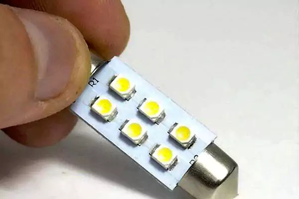
SMD: Surface Mount Device
This term refers to parts, and is specifically used to describe those electronic parts that can use SMT processes or technologies.
SMT: Surface Mount Technology
This term refers to a technique, a technique for soldering electronic parts to the surface of a circuit board.
 To clarify this further with a metaphor, think about the car as a complete product. The car is composed of many parts (tires, doors …), and those parts of the car could also be called it’s devices. Driving a car means you know how to properly utilize these parts. Using technology, like driving a car, usually takes a long time to learn, and practice makes perfect.
Let’s return to the subject of SMT (Surface Mount Technology). According to the literal meaning, it is a technique for soldering electronic components on the surface of a printed circuit board (PCB), using wave soldering technology. This is different from the earlier through-hole components. This SMT technology can reduce the volume of electronic products significantly to achieve lighter, thinner, shorter and smaller boards. Therefore, the traditional through-hole plug-in can be compared to the previous vacuum tube TV, and SMT technology can be compared to LCD TV.
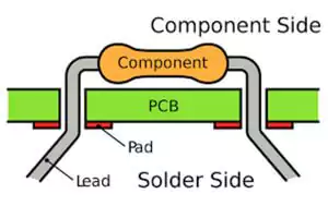
When early electronic components first came out, there was only the traditional through-hole technology (THT, Through-Hole Technology) (DIP, Dual-Inline Package, which is the name of the plug-in IC of the early double-row foot), so the electronic components had to be designed for extra welding. The feet had to be inserted through the circuit board to be able to solder the parts to the circuit board. However, the soldering feet of the through-hole parts have a minimum size limitation, because at a certain size the soldering feet can be easily broken or may break by accidentally dropping the soldering feet. 5x5mm is about the smallest that a through-hole part can be. But SMD parts can achieve 0.4×0.2mm, and even smaller. This is why the original Black King phone was as big as a brick, and could only be used for calls. The modern smartphone is less than 1/5 the size of the Black King, and has a lot more features.
What kind of technology does SMT use to solder electronic components to circuit boards? It’s called solder paste. The solder paste is printed on the pads that need to be soldered, and then the electronic parts are placed on them. The soldering feet should be placed just right on the solder paste. After that, the board is placed in a high-temperature reflow furnace. The maximum temperature in the furnace must be higher than the melting point of the solder paste, but not so high that the electronic components will be burned. The reflow will then melt the solder paste into liquid. When it becomes a liquid the solder paste will cover the soldering feet of the electronic parts. After the temperature comes down the solder paste will return to the solid state, and the electronic parts will be soldered onto the circuit board.
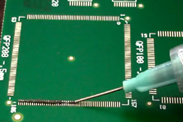 This method of solder paste printing is a bit like using a cover letter or lacquer pattern when painting.
What advantages and benefits does SMT have for electronic products?
Electronic products can be designed to be thinner, lighter, and shorter. As parts become smaller, the usable area of the circuit board will be smaller than the previous through-hole parts.
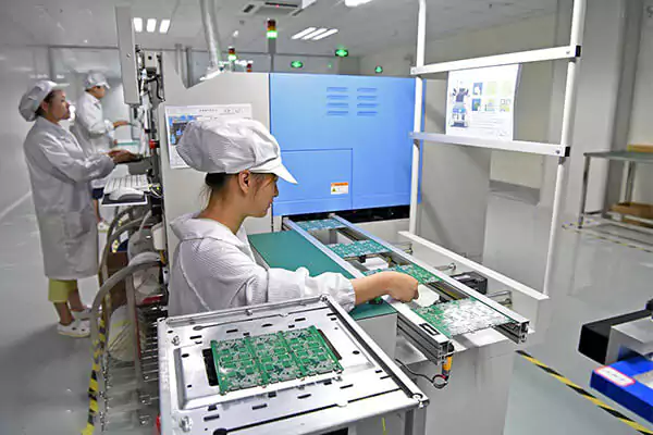
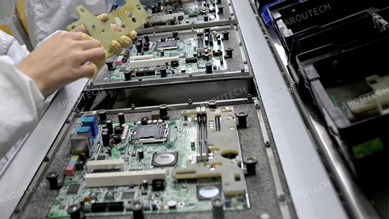
This technology is also suitable for mass production. Because SMT technology eliminates most manual plug-in operations and the placing of electronic components is done by machines, it is more suitable for the mass production of high-quality products, and the process is more stable than through-hole plug-ins.
It also lowers the production costs by reducing manpower and hours, because the through-hole parts rely on manual placement while SMT parts rely on machine settings.
Latest insights & related news
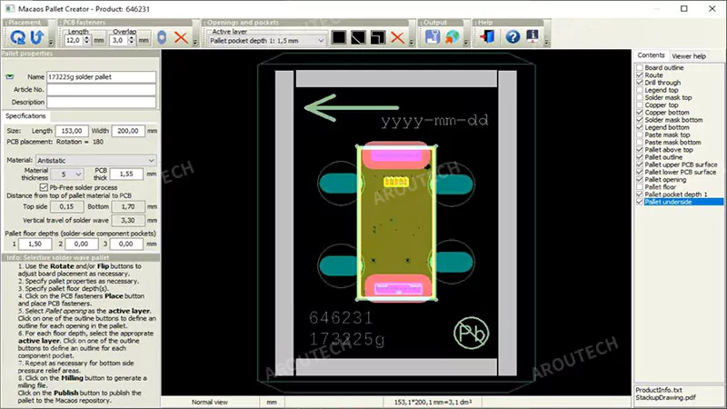
What is a Wave Solder Pallet and Why is it Critical for Your PCBA Production?
Are you struggling with inconsistent soldering, high defect rates, and production bottlenecks? You’ve optimized your process, but the root cause might be an overlooked, yet essential, tool. A wave solder pallet is a custom-machined carrier, typically made from a high-performance composite solder pallet material, that precisely holds, masks, and protects a Printed Circuit Board Assembly […]
How Can You Master Solder Pallet Design for Flawless Soldering?
You’ve chosen the perfect material, but your soldering results are still inconsistent. The problem often lies not in the material itself, but in the blueprint used to shape it. A comprehensive solder pallet design guide involves mastering four areas: selecting the correct material thickness, implementing effective hold-downs, designing precise masking walls, and ensuring compatibility with […]
How Do You Choose the Right Solder Pallet Material for Your Process?
You know what a solder pallet is and why it’s critical. But now you face the core decision: choosing the material. Pick the wrong one, and you could face warping, chemical damage, and a short pallet lifespan, undermining your entire investment. To choose the right solder pallet material, you must conduct a solder pallet material […]